Mv network diagrams for feeding secondary switchboards and mv/lv Schematic of the converter, with entire mv circuit inside of the tank Voltage source current circuit ideal figure diagram practical characteristics shown shows below
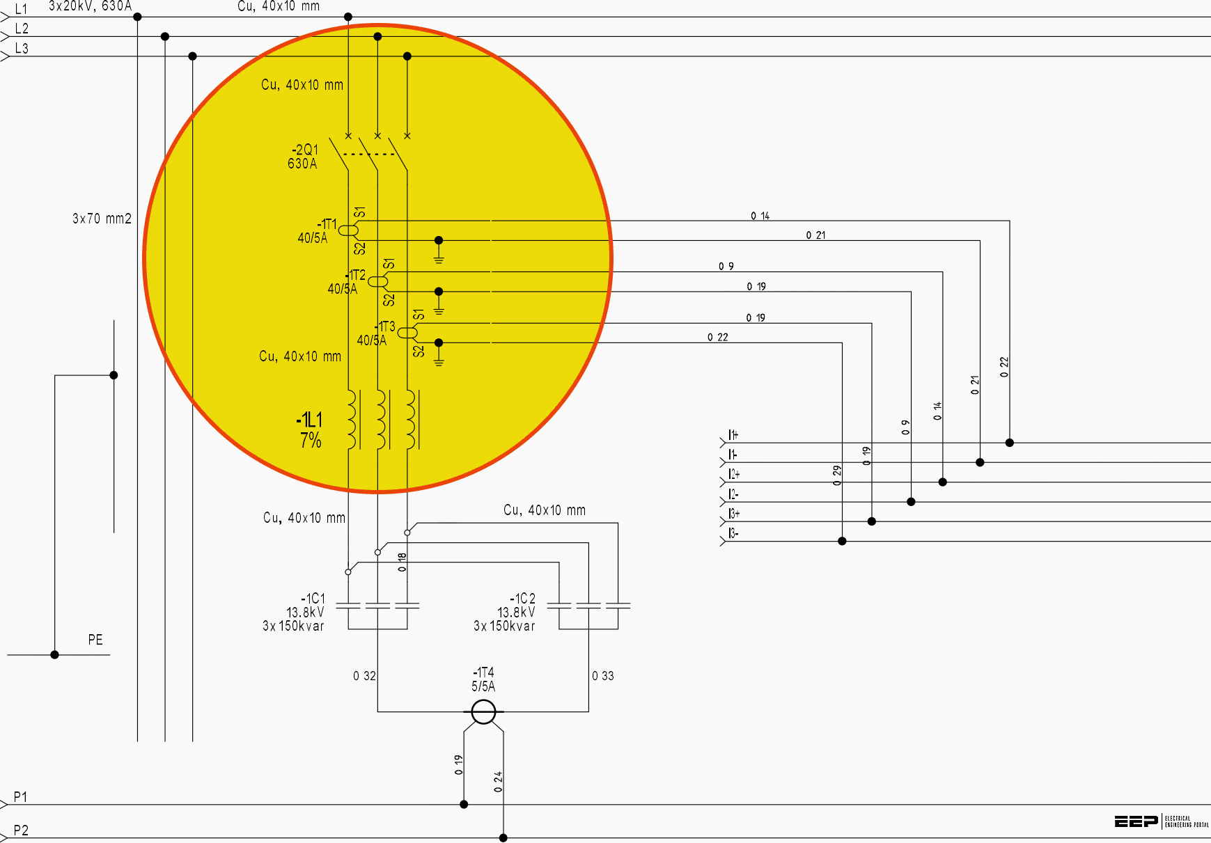
Mv Panel Wiring Diagram
Schematic of the current source circuit
Mv network voltage estimation errors
Circuit implementation of mvsm system working in a true voltage-modeRole of 12 mv connection point detailed single line diagram Multiple power source circuit analysisEquivalent circuit of a mv distribution network in case of a ccf.
Find the voltage source in the circuit – valuable tech notesMv panel wiring diagram Joint model of the mv circuit and the turbines of a park.Configuration of the voltage source circuit after design.

2 schematic mv-4
Voltage source inverter (vsi) operationWhat is voltage source and current source Mv errors estimationLv diagrams 20a transformers switchboards portal.
What is current source inverter? working, diagram & waveformsEquivalent diagram of mv power network with consideration of line Circuit and wiring diagramsSchematic showing the mv network architecture connected with multiple.

(a). schematic of the mv process. compliances and flow resistances are
Inverter voltage vsi principle invertersEquivalent circuit model of the hv/mv station. Equivalent mv circuit ccfBlock diagram of controller circuit for mv stage of proposed sst.
Schematic representation of mv structure. source: rota pa et al., natMva calculation method Solved 2 for the given circuit, the output voltage in mv andBasic diagram of the modeled mv network..

-logical scheme of the mv system
Short circuit current calculation-mva method : power systemsCircuit diagram (800 mv input) Circuit diagram of mvf.What is current source inverter? single-phase current source inverter.
Circuit multiple analysis source power loop currents thus define mesh above fig1 gifWhat is a voltage source inverter (vsi)? Mv source circuit diagramEducatore genuino elettronico inverter h bridge mosfet circuit perizoma.

Mv parallel networks converters microgrids
.
.